Friday, July 24, 2009

Maiden voyage

With a couple batteries tied to the radiator mounts I was able to drive up and down the driveway a few times before the batteries got weak. Like I said, the throttle is really jumpy and there is a wobble in the motor front plate, which I'm affraid might be serious. The next step is to get the battery racks built and installed and string some cables to the trunk.

Kelly controller error

I had a few set backs today. I first got the 2,4 error "Throttle signal is higher than configured dead zone at power-on." I had the ground and 0-5v output reversed. Then I got the error 2,2 or "Internal Voltage Error", which says "The controller is damaged". I guess I got a bad one.

Later: It turns out I had the potentiometer wired wrong. The 5v goes to the COM (left), Ground to the N.O. (middle), and the 0-5V throttle to N.C. (right). It works now. The throttle is very quick and the car lurches forward or back, not sure what that is.


Wednesday, July 22, 2009

Solar Bug

Steve Titus lent me a couple batteries for testing. Here he is standing next to his Solar Bug. It is a 72v EV with a solar panel on the top. With 3-4 amps from the PV panel he should be able to get 10-15 miles per day from the sun!

Saturday, July 18, 2009

Makin' cables

With the control box in place and the low voltage wiring ready, now time for the high voltage cables. The orange ultraflex cable is much easier to work with in tight spaces, like the control box, than the black but it is twice as expensive. In this picture is the Noalox anticorrosion gel and the hammer crimper. I've found pounding with a hammer on the cement floor give the best results.

Friday, July 17, 2009

Temperature sender

This is the original temp sender from the engine. It is a thermistor or temperature resistor connected to the temp gauge on the dashboard. When the temp goes up the resistance goes down. I'm mounting it to the controller to monitor the temp from the drivers seat. The controller operates up to 90C (195F) and will shutdown at 100C (212F). This corresponds to a typical 195F thermostat in a car so the gauge should read about halfway when the controller gets hot.


Control box mounted


There was a mounting bracket already in the engine bay and a 6" angle bracket from Ace fit perfectly to one of the screw holes for the clutch, which is gone. The mount is bomber and the hood even closes, which is a plus. Also, there is room for battery racks in front and behind. The controller is Kelly 144v with regen from cloudelectric for $875.


The Kelly KDH requires a 5V input instead of just the 5ohm input from the existing potbox wires. So, wiring the 5V output from the controller into the potbox, plus the ground and the 5V output of the potbox.


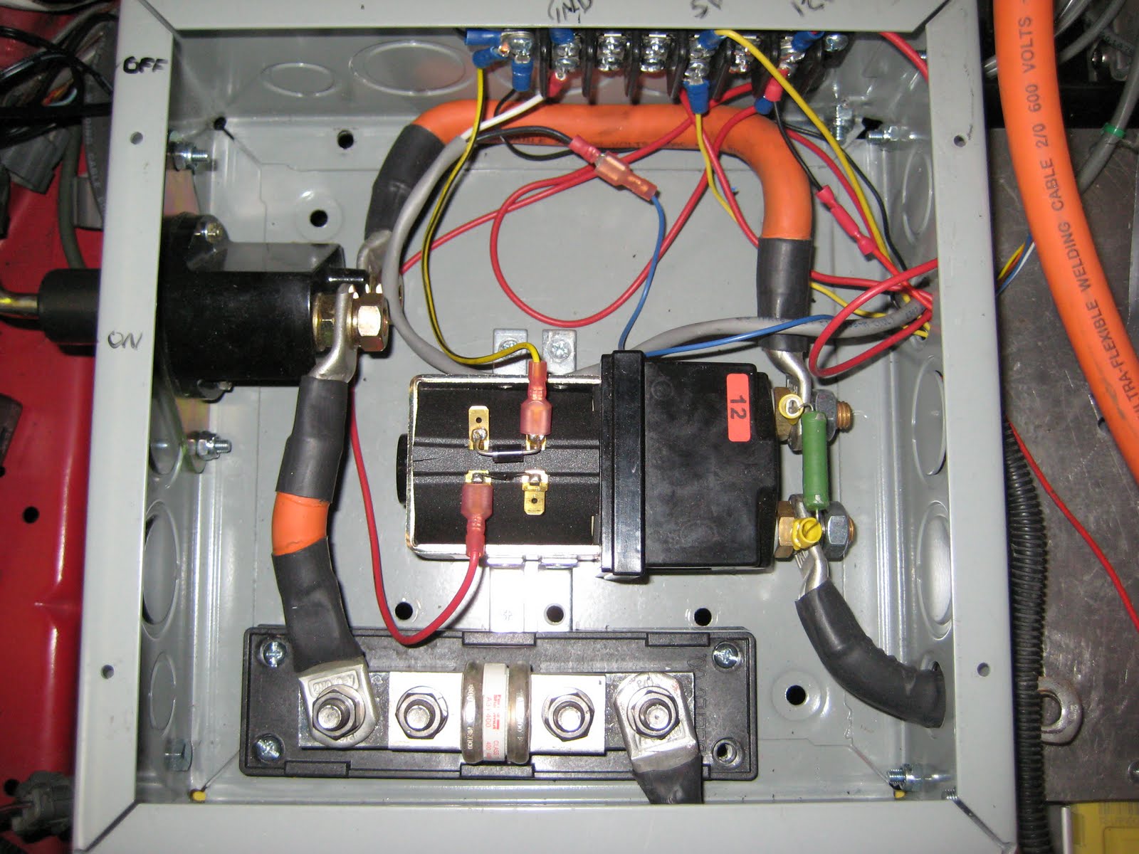
Sorry I'm so color blind with my wiring. The yellow-black wire should be black (gnd) and the blue wire (from the throttle's black wire "signal") should be green. I've used yellow for 5V from the controller to the throttle.

Wednesday, July 15, 2009

Control box and controller

The control box is starting to take shape. I picked up a wiring box at home depot and have been drilling holes in it for 2 days. I've found a good place to mount it just above the transmission. The controller will mount off of the side of it. Once I get everything bolted down I can start wiring it.

Tuesday, July 14, 2009

EVs in the hood

It turns out that the neighborhood I live in is a hot bed of EV activity. An engineer for the Barefoot ATV lives nearby. I drove one today, very nice. It has really smooth accelerating and has aggressive regen so it stops almost without braking.

Last week I drove Steve Titus' Solar Bug
, which has a solar panel on the top. It was a sunny day and the 48v panel was producing 3amps, which should recharge the batteries in a few hours after driving a few miles.

Monday, July 13, 2009

Potentiometer

I've installed the potbox in about the same place as the last car. It was more manageable to attach it directly to the firewall than near the controller or heatsink. Plus the accelerator cable was much shorter on the del Sol than the older civic. Notice the remnants of the wiring harness. I'll wrap that in some plastic cable wrap to protect it.

Friday, July 3, 2009

Wiring harness


This manual has good wiring diagrams of the '93 del Sol. Along with tips from this blog Open Source Civic EV Kit: Figuring out the wiring harness I was able to get the backup lights working. Testing the speedometer will have to wait until it is drivable. Ironically, the "check engine" light is now on. So, I'll have to remove fuse #15.

Wednesday, July 1, 2009

Motor mount


Using a grinder I cut a channel for the motor mount plate. The plate is 1/8" steel. There are 2 mounting holes on the auxiliary side of the motor.